Modern engineering applications need reliable methods for creating, editing, analyzing, and managing three-dimensional models. geometry modelling provides the foundation for these workflows, allowing software to represent physical products as accurate digital objects. From individual mechanical components to complex assemblies, effective modelling technology helps engineering teams move from initial concepts to detailed digital designs.
A well-planned modelling workflow is about more than creating shapes. Developers must consider how geometry is constructed, modified, visualized, validated, stored, and transferred to other systems. Building these capabilities into an application requires a combination of geometric algorithms, topology management, data handling, and user-focused tools.
Defining the Modelling Requirements
The first stage of an engineering modelling workflow is understanding the type of geometry the application needs to handle. A mechanical design tool may focus primarily on solids, while an application for industrial or consumer products may require sophisticated surface modelling.
Other applications may work with wireframes, imported CAD files, assemblies, or a combination of several representation types.
Clearly defining these requirements helps developers choose suitable geometric technologies and design an application architecture around actual engineering needs.
Creating Basic Geometry
Most modelling workflows begin with fundamental geometric entities. Points, curves, edges, surfaces, and solid primitives can serve as building blocks for more complex designs.
Developers can use these entities to create cylinders, boxes, spheres, profiles, and other basic forms. Combining these elements allows users to construct increasingly detailed components.
Accurate calculations are important at this stage because errors in basic geometry can affect later operations.
Developing Complex Shapes
Once basic geometry has been created, engineering applications often need tools for developing more complex forms. Boolean operations can combine or subtract solids, while surface operations can create sophisticated external shapes.
Curves may be used to define profiles or guide surfaces. Operations such as trimming, extending, offsetting, and transforming can provide additional control over the final model.
A robust workflow should allow these operations to work together while maintaining consistent geometric relationships.
Managing Topology
Geometry describes the mathematical form of a model, while topology describes how its elements connect. Faces, edges, and vertices need to maintain appropriate relationships as the model changes.
Topology management is particularly important when users perform operations that modify existing geometry. A change to one part of a model can affect connected faces and edges, so the application must update these relationships correctly.
Reliable topology can help maintain model integrity throughout the editing process.
Supporting Assembly Workflows
Engineering products frequently consist of multiple components rather than a single body. Assembly workflows therefore need methods for organizing individual parts and their relationships.
Applications may need to manage component hierarchies, names, identifiers, and properties. Users should be able to navigate assemblies and select individual components without losing sight of the overall product structure.
Large assemblies should be included in performance testing because their processing requirements can differ significantly from those of individual parts.
Visualization and Model Inspection
Users need effective ways to inspect the geometry they create. Visualization tools can support rotation, zooming, selection, measurement, sectioning, and different display modes.
Interactive inspection can help engineers identify design issues and understand complex structures. For developers, visualization performance should be evaluated alongside geometric processing because both contribute to the overall user experience.
Validation and Quality Checking
Before a model moves to manufacturing, simulation, or another downstream process, it may need to be validated. Applications can provide tools for checking geometry, identifying potential inconsistencies, and confirming that required model information is available.
Validation can also be incorporated into automated workflows. This can help organizations identify problematic files before they are passed to another engineering system.
Data Exchange and Conversion
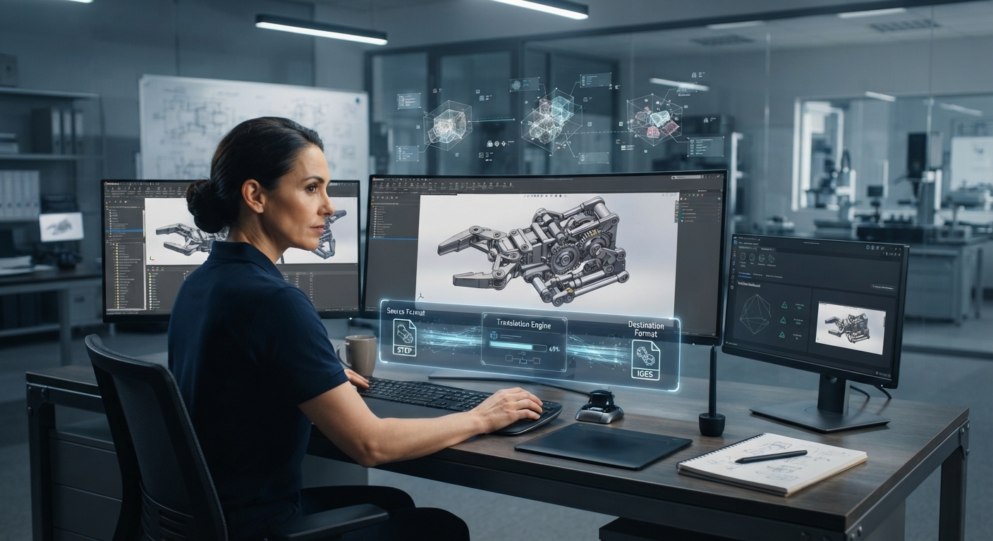
Engineering software often needs to work with models created by different applications. Import and export capabilities can therefore become an important part of the modelling workflow.
Developers should consider which file formats users require and how effectively the application can handle translated geometry. Depending on the project, assemblies, attributes, metadata, and other information may also need to be preserved.
Testing with real engineering files can help identify compatibility issues early.
Performance and Automation
As engineering models become larger, performance becomes increasingly important. Developers should evaluate geometry operations, model loading, visualization, memory usage, and file processing with realistic datasets.
Automation can also improve efficiency by supporting batch conversion, model validation, data extraction, or other repetitive tasks. Proper error handling ensures that individual processing failures can be identified without disrupting an entire workflow.
Building an Effective Modelling Workflow
A successful engineering modelling workflow connects geometry creation with editing, topology management, visualization, validation, assembly handling, and data exchange. Each stage contributes to the usefulness and reliability of the final application.
By defining requirements clearly, testing with representative engineering models, and using dependable geometric technology, development teams can create software capable of handling complex 3D data. A structured modelling workflow can ultimately support engineering organizations throughout design, collaboration, manufacturing preparation, and other stages of the product development process. Engineering 3D Software from Geometric Modeling to Data Conversion
#MCAD #CADSoftware